How to Schematic diagram of RO Plant with RO Components
Por um escritor misterioso
Last updated 12 março 2025
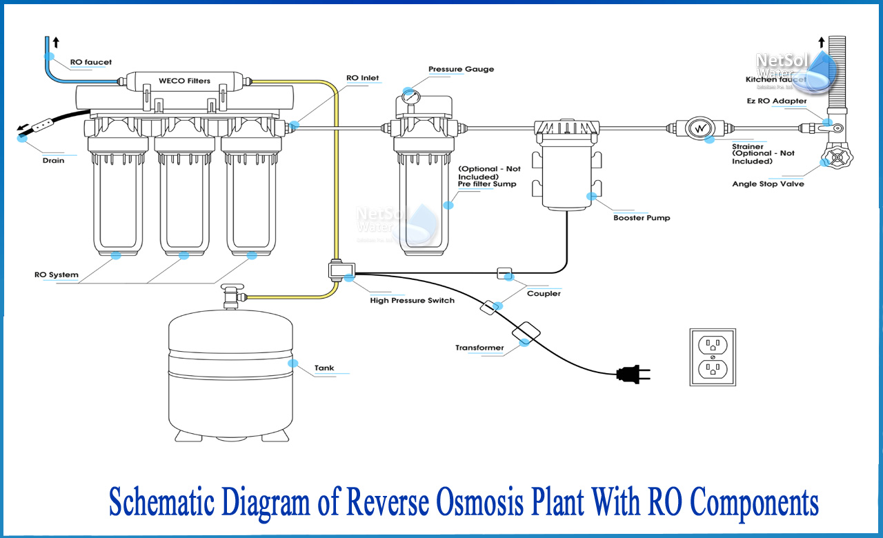
How to Schematic diagram of RO Plant with RO Components? The separation takes place in a dense polymer barrier layer in reverse osmosis membranes. Because Reverse
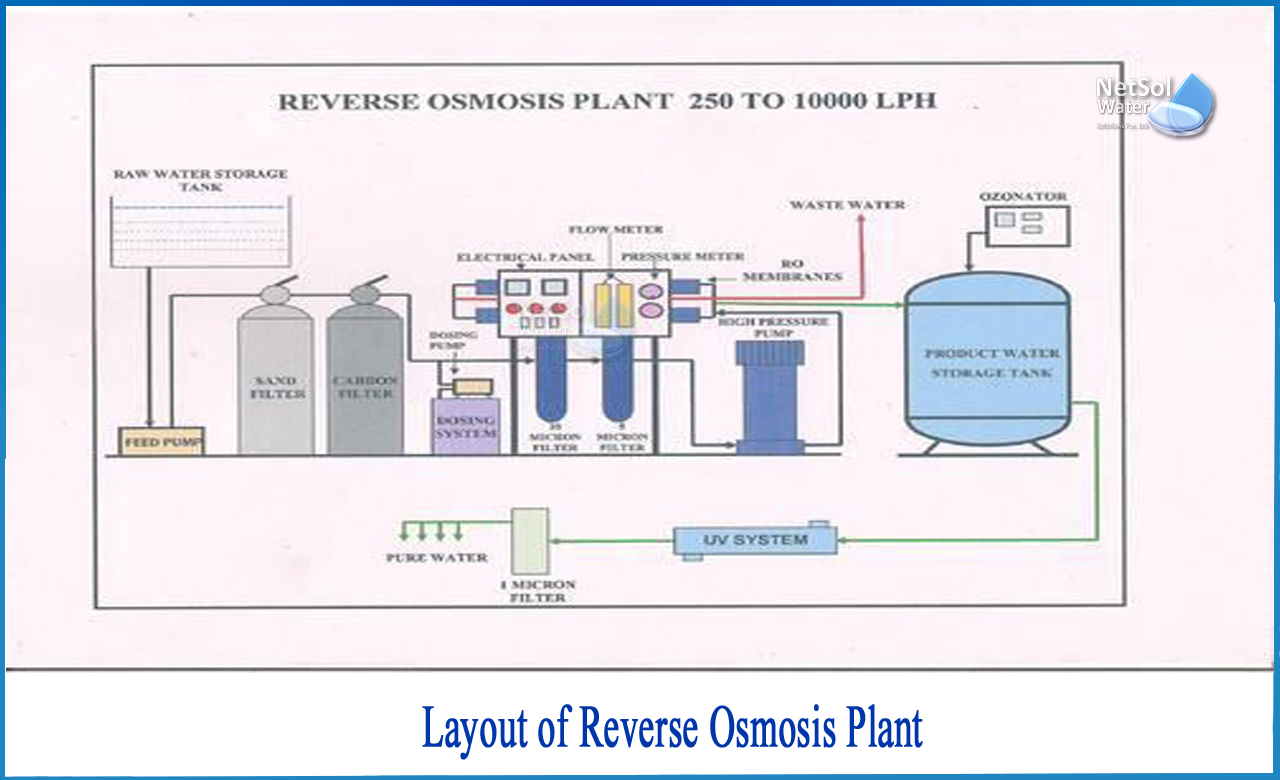
What determines the Layout of RO plant

Schematic diagram of RO system

The Basics of RO Plants

6-stage Reverse Osmosis System with Booster Pump & UV Sterilizer

Schematic diagram of an RO desalination treatment plant
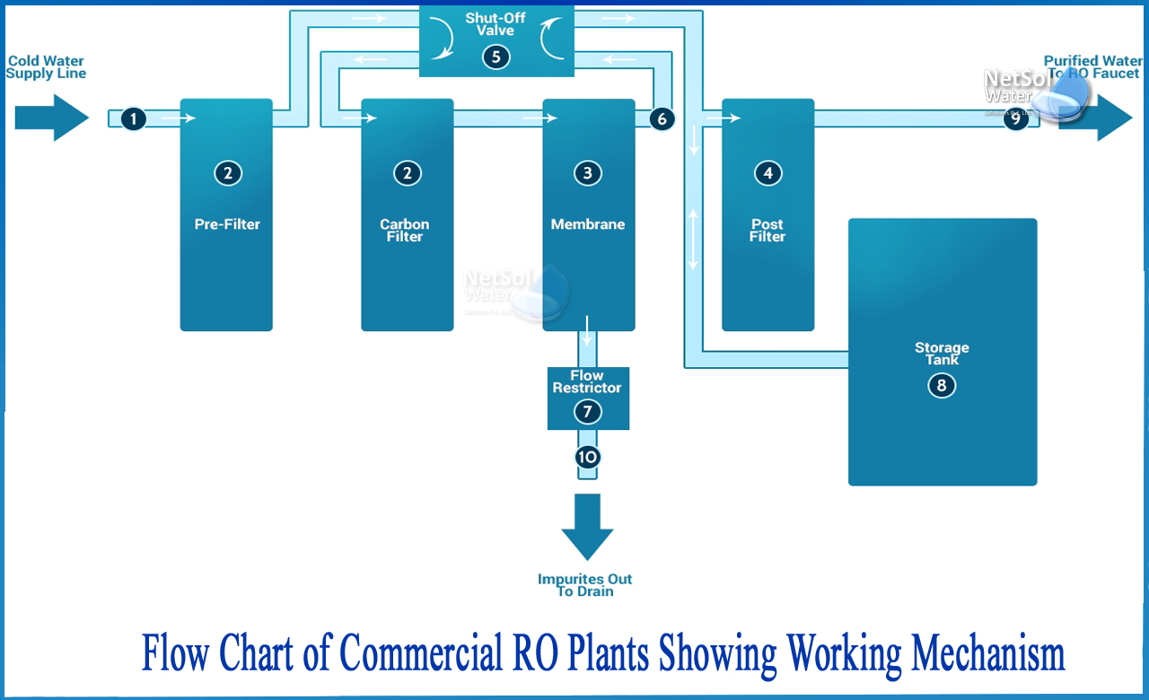
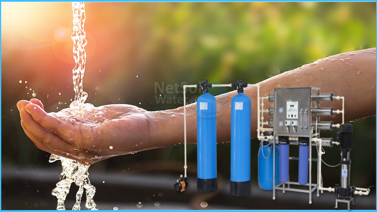
How does a commercial RO Plant work - Netsol Water

a) Indigenously fabricated RO plant (b) Flow Sheet diagram of
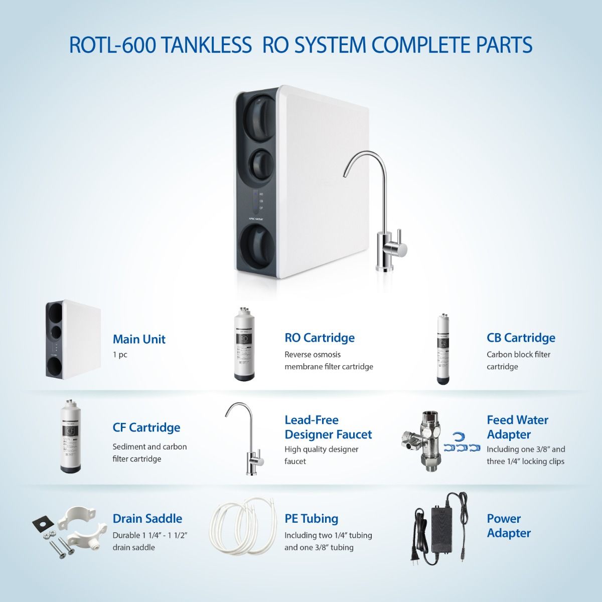
ROTL-600 - 3 Stages Premium Reverse Osmosis Water Filtration
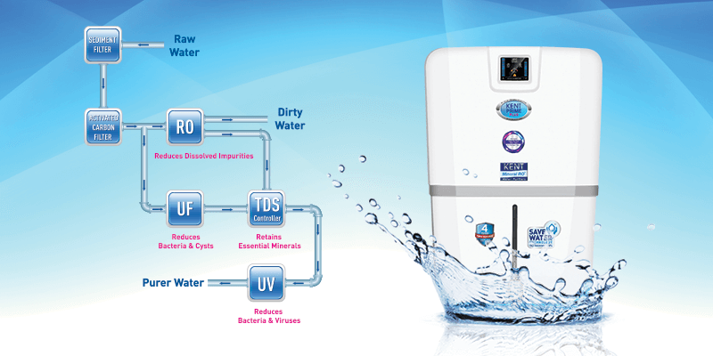
How Reverse Osmosis Works? Working of RO Water purifier System

How to increase output of your RO or RODI System

Max Water 9 Stage 50 GPD (Gallon Per Day) RO (Reverse Osmosis
Recomendado para você
-
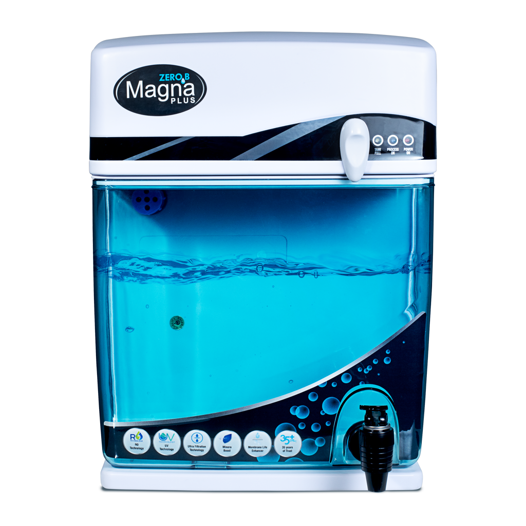 Magna Plus RO+UV+UF12 março 2025
 -
 Reverse osmosis - Wikipedia12 março 2025
 -
 Why is government focusing on installing RO plants in schools?12 março 2025
 -
 Shop - Water Purifier Manufacturer One Stop RO Solution12 março 2025
 -
 Buy True RO Water Purifier Mineral Booster - WW140NP12 março 2025
 -
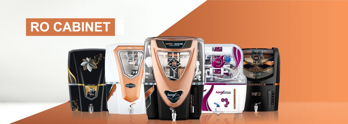
 RO Cabinet Shine - Water Purifier Manufacturer12 março 2025
 -
 Buy LG 8L RO+UV Water Purifier Online - WW145NPW12 março 2025
 -
 Native RO Water Purifier12 março 2025
 -
 Always Swift 15L 15 L RO + UV + UF + TDS + Alkaline Water Purifier12 março 2025
 -
 Buy KENT Pearl 8L RO + UV + UF + UV-in-tank + TDS Water Purifier with Detachable Storage Tank and Zero Water Wastage (White) Online - Croma12 março 2025
você pode gostar
-
 moomoo.io - How can I buy a hat with my gold? - Arqade12 março 2025
 -
 Pizza Pizza on X: This Just In: NEW Super Pan Pizza with thicker & fluffier crust now available at Pizza Pizza! / X12 março 2025
 -
 ArtStation - commission goku ssj 2 vs majin vegeta ssj212 março 2025
 -
 Cooking Simulator - Pizza -- Is it worth it?12 março 2025
 -
 More Gen 1 Alola Pokemon Have Leaked12 março 2025
 -
 DVD Filme Mazzaropi em Casinha Pequenina Volume 9 - Accordes Magazine12 março 2025
 -
 The Definitive 2023 Guide to the Russian Flag - History, Meaning, & Colors12 março 2025
 -
Tico e Teco Lanches adicionou uma - Tico e Teco Lanches12 março 2025
-
 LANÇOU!! 13 NOVOS *EXCLUSIVOS* CODES SECRETOS no KING LEGACY CODIGOS! (King Piece Codes) - ROBLOX12 março 2025
 -
 Baixe o RVC Mobile MOD APK v9.21.2 para Android12 março 2025
